Rs485 Cable - What Is It?
페이지 정보

본문

Pre-coded device drivers configure the SPI for a standard data format, and it is easy to customize a data format and baud rate for your application. The two lowest order bits in the SPCR control register, named SPR1 and SPR0, determine the data exchange frequency expressed in bits per second; this frequency is also known as the baud rate. The SPIE bit in the SPCR (SPI control register) enables SPI interrupt handling. RS485 is a serial data transmission interface standard that enables communication with sensors attached to the same bus (wires). The flexibility and power of the 68HC11’s serial peripheral interface supports high speed communication between the 68HC11 and other synchronous serial devices. The Serial Peripheral Interface, SPI, is a fast synchronous serial interface. It provides a convenient means of connecting the QScreen Controller to a variety of peripheral devices, including analog to digital and digital to analog converters, real time clocks, and other computers which use high speed communication. The SCK pin’s synchronous clock signal has configurable phase, polarity and baud rate so that it can interface to a variety of synchronous serial devices.
It also defines three generator interface points (signal lines); A, B and C. The data is transmitted on A and B. C is a ground reference. The CPOL and CPHA bits configure the synchronous clock polarity and phase and specify when valid data is present on the MISO and MOSI data lines. Any required SPI output signals must be configured as outputs, either by calling InitSPI() or by setting the appropriate bits in the Port D data direction register DDRD. Battery modules must be turned ON. For the example, we will use 4 battery modules on the stack. For the QScreen, /SS is not used for SPI communication because it is used to control the direction of the RS485 transceiver; you can use any digital I/O line as a /SS signal. SC, G or reference, the common signal reference ground used by the receiver to measure the A and B voltages. In general, all devices on a network should use the same phase, polarity, and baud rate clock signal. The rate of data transmission is expressed in bits per second, or baud. There are three flag bits implemented in the SPSR (SPI status register).
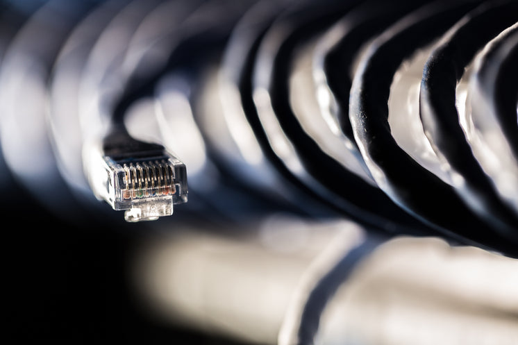
There are many possible configurations of master/slave networks. Bus Probes are very compact (measuring only 40x36mm externally) and sport an attractive look and feel. Two Tibbo Project System (TPS), Gen. 2-compatible Tibbo BASIC applications for the setup and testing of Bus Probes are available: BP-Tester-UI and BP-Tester-Web. Bus Probes can be configured and tested using our web-based test app (you will need to connect the probes to your PC or Android smartphone via our Web485 board). 04), a Web485 board, and the necessary cables. Anti-inteference layer: Rs485 cables are designed with 2 anti-inteference layers to shield the internal conductors. RS485 avoids this issue which also allows for shielding of the cables to prevent noise. All in all, RS485 really allowed full automation possible with its ability to connect so many devices at once. One very common example in the automation world is remote control of VFDs or Variable Frequency Drives. Converters between RS-485 and RS-232 are available to allow a personal computer to communicate with remote devices. These are used in programmable logic controllers and on factory floors. These distances I'm talking about are greater than 100 meters. Users can utilize a longer cable, up to 1200 meters or 4000 feet.
You aren’t limited to fifty feet of cable like with RS232. What made it such an advancement over RS232 was the fact that it could transmit not only a single device to device transmission, but also a communications bus to connect multiple devices at once. At any given time, only the master and a single "active" slave communicate. So make sure that your screen doesn't go to sleep while you're upgrading and that every single module has been upgraded as well. If you've already downloaded and installed the Software, go to the section called "Upgrading the Modules". Section 4 defines the electrical characteristics of the generator (transmitter or driver), receiver, transceiver, and system. The next section describes the registers that configure and control the QScreen Controller’s SPI. This chapter describes those drivers, and presents code that makes it easy to configure the SPI for different data transfer rates and formats.
If you loved this article and you would certainly like to receive more info concerning rs485 cable kindly see our website.
- 이전글Dating Techniques For The Shy Woman 24.06.21
- 다음글Cracking the Code: The Enigmatic World of Lotto Number Statistical Analysis 24.06.21
댓글목록
등록된 댓글이 없습니다.


