The most effective explanation of RS485 Standard I've ever heard
페이지 정보

본문

If more than one segment happens to be turned on, the software within the SMINI defaults to using the baud rate corresponding to the highest switch segment with an "on" setting. While the conversion is "transparent" the software must be able to communicate with the expanded network features. Line RC7, Pin 26, is U1's serial data input Receive (RX) line, while RC6, Pin 25, is the serial data output Transmit (TX) line. Each of the SMINI output ports is configurable for standard current-sinking or alternate current-sourcing. The majority of C/MRI applications use current-sinking whereby railroad devices are activated, i.e. turned on, by the SMINI completing the ground connection. The SMINI has six 8-bit output ports labeled as Ports A, B and C for "Cards 0 and 1." Similarly, the three 8-bit input ports are labeled as Port A, B and C for "Card 2." Each I/O port includes an important buffer between the railroad’s connection to the SMINI card and the PIC16F877. RB6 - RB7 used as outputs to drive 2 of the 3 input buffer enable lines for separately activating 2 of the 3 SMINI input ports. One of these port select lines connects directly to the enable (EN) inputs for each of the port I/O buffer functions.
The 24-pin inputs are noted as Card 2 along the right edge. Up to 32-nodes (drivers and receivers) are allowed on one multi-drop, bi-directional network. The SMINI includes circuitry for two 24-pin output cards and one 24-pin input card. It also means that the transmission loses some of its "attenuation budget", because the signal amplitude gets closer to the receivers' nominal voltage sensitivity (the signal gets attenuated right at the driver's output). Alternatively, with current-sourcing the SMINI provides the actual voltage that activates the railroad device. Each railroad device being interfaced simply connects directly to one or more of these pins. Although all the I/O lines are physically on the same SMINI card it is convenient to talk about them as being separate (I/O) cards within the same (SMINI) card. To support a distributed serial system, multiple SMINI receiver and transmitter ICs, U6 and U7, are connected in parallel on the same two sets of two wires leading back to the PC. Three wires are used with RS232. There are also 9 separate I/O control wires - typically called port select or enable lines - joining the 877 to each of the 9 I/O buffering functions.
The arrows in Fig. 4-3 indicate the direction of signal flow, and double lines with a slash and number indicate multiple parallel wires - four, seven or eight in our case. Each signal is carried by a pair of wires and is thus a differential data transmission system. This provides easier system operation and debugging capability. If you are interested in how the SMINI works, and in debugging it in case of trouble, I will explain what the SMINI does and give you a tour of its schematic. PIC processors are the most popular family of microcontrollers and the 877 is ideally suited for our interfacing needs. Do not worry about having to do any PIC programming. Programming the PIC16F877 FLASH memory requires a special PIC Micro Programmer package. The heart of the SMINI is part U1, a Microchip Technology PIC16F877-20/P Microcontroller with built-in FLASH memory, making it a smart interface. The PIC16F877 performs all the bookkeeping as to which particular bit the computer is sending and whether it is part of an address or data. Odd (O) - the parity bit is set so that the number of "logical ones (1s)" has to be odd. The 7-segment switch can set 128 unique addresses, allowing up to 128 SMINI cards in an RS485 system.
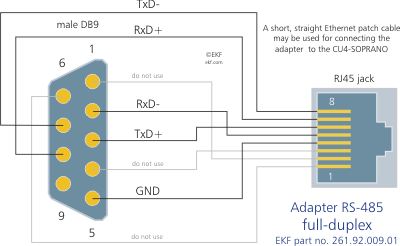
It allows them to talk via RS485 Modbus. RS485 is used as the physical layer for many standards and proprietary automation protocols to implement control systems, most commonly Modbus and Profibus. Therefore RS485 will be in use for many years in the future. When you hear that buzzword for the fist time, you will likely imagine three neat isolation gaps, surrounding the three ports (local data port, the longer-haul line interface, and the power input). 12V PSU rail to pin 9 in the COM port (which can otherwise be jumpered for RS232/422/485), instead of the standard function of a "ring indicator" input. RE2 used as output to drive the green SMINI status indicator LED. My explanation is that the RS485 bus drivers' output impedance is optimized (matched) for the typical 120Ω transmission line (the driver's output impedance should actually be half that value, because the driver feeds two sections of the TML in parallel), and if a lower impedance transmission line is attached to the driver, the drivers' output sags accordingly. Compatible with TTL/RS485 standard, converting the TTL signal into a balanced differential RS485 signal, supporting full-duplex communication. It is well suited for transmitting smaller data blocks over long distances, using a twisted differential signal pair for both TX and RX signals, allowing for half-duplex asynchronous communication.
- 이전글prandin: Acheter enyglid en Belgique sans ordonnance médicale 24.05.27
- 다음글Preisinformationen: kaufe diltiazem 60 mg in Spanien 24.05.27
댓글목록
등록된 댓글이 없습니다.


